EP-KR / EP-KRV stud type track rollers cover outside diameters from 13 mm through 90 mm, with threaded studs from M5×0.8 to M30×1.5. The family is intended for cam and track-following mechanisms where the outer ring runs directly against a mating surface. Selection should begin with the physical interface—outside diameter, ring width, stud thread and stud length—then move to speed, load, track geometry, lubrication and the ordered outer-surface configuration.
Match D*, C, D1, thread, B/B1/B2 geometry and corner details before assuming that a legacy designation will fit.
The outer surface may be cylindrical or spherical depending on the design. Confirm the required contact geometry for the actual mating track.
When the KR/KRV family is supplied with an eccentric arrangement, the designation changes to KRE / KRVE. State whether adjustment by eccentricity is required.
Grease retention, sealing and special lubricant needs depend on the ordered configuration and operating environment. Put clean, washdown or food-related requirements in the RFQ.
IKO CF and WERB NAKD designations are useful identification references. Final replacement still requires dimensional and configuration confirmation.
Series selection table
This table brings the main screening variables into one place. C and C0 are included as the rating figures shown for the family, but the available rating table does not print a load unit; request a confirmed engineering datasheet before using those two values in calculations.
| EP model | D* (mm) | e (mm) | Stud thread | Basic load C* | Basic load C0* | Speed ref. (rpm) | Mass (g) | IKO reference | WERB legacy |
|---|---|---|---|---|---|---|---|---|---|
| EP-KR13 / EP-KRV13 | 13 | 0.25 | M5x0.8 | 280 | 180 | 29,000 | 16 | CF5 | NAKD13 |
| EP-KR16 / EP-KRV16 | 16 | 0.25 | M6x1 | 270 | 170 | 25,000 | 18 | CF6 | NAKD16 |
| EP-KR19 / EP-KRV19 | 19 | 0.25 | M8x1.25 | 300 | 210 | 20,000 | 28 | CF8 | NAKD19 |
| EP-KR22 / EP-KRV22 | 22 | 0.3 | M10x1.25 | 410 | 320 | 17,000 | 44 | CF10 | NAKD22 |
| EP-KR26 / EP-KRV26 | 26 | 0.3 | M10x1.25 | 410 | 320 | 17,000 | 58 | CF10-1 | NAKD26 |
| EP-KR30 / EP-KRV30 | 30 | 0.3 | M12x1.5 | 590 | 450 | 14,000 | 87 | CF12 | NAKD30 |
| EP-KR32 / EP-KRV32 | 32 | 0.3 | M12x1.5 | 590 | 450 | 14,000 | 90 | CF12-1 | NAKD32 |
| EP-KR35 / EP-KRV35 | 35 | 0.35 | M16x1.5 | 850 | 760 | 10,000 | 169 | CF16 | NAKD35 |
| EP-KR40 / EP-KRV40 | 40 | 0.35 | M18x1.5 | 1,180 | 1,220 | 8,500 | 247 | CF18 | NAKD40 |
| EP-KR47 / EP-KRV47 | 47 | 0.35 | M20x1.5 | 1,630 | 1,690 | 7,000 | 386 | CF20 | NAKD47 |
| EP-KR52 / EP-KRV52 | 52 | 0.35 | M20x1.5 | 1,630 | 1,690 | 7,000 | 461 | CF20-1 | NAKD52 |
| EP-KR62 / EP-KRV62 | 62 | 0.4 | M24x1.5 | 2,160 | 2,210 | 6,500 | 790 | CF24 | NAKD62 |
| EP-KR72 / EP-KRV72 | 72 | 0.4 | M24x1.5 | 2,160 | 2,210 | 6,500 | 1040 | CF24-1 | NAKD72 |
| EP-KR80 / EP-KRV80 | 80 | 0.5 | M30x1.5 | 2,830 | 3,700 | 5,000 | 1550 | CF30 | NAKD80 |
| EP-KR85 / EP-KRV85 | 85 | 0.5 | M30x1.5 | 2,830 | 3,700 | 5,000 | 1740 | CF30-1 | NAKD85 |
| EP-KR90 / EP-KRV90 | 90 | 0.5 | M30x1.5 | 2,830 | 3,700 | 5,000 | 1950 | CF30-2 | NAKD90 |
Filter the EP-KR / EP-KRV range
Detailed main dimensions
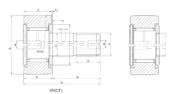
Use the drawing and dimensional table together. D* and C define the outer-ring envelope; D1, G1 and the thread identify the stud interface; B max, B1 max, B2 and B3 describe the axial mounting envelope; C1 and rs min are relevant around shoulders and corner clearances.
| EP model | D* | C | D1 | Stud thread | G1 | B max | B1 max | B2 | B3 | C1 | rs min |
|---|---|---|---|---|---|---|---|---|---|---|---|
| EP-KR13 / EP-KRV13 | 13 | 9 | 5 | M5x0.8 | 7 | 10 | 23 | 13 | — | 0.5 | 0.3 |
| EP-KR16 / EP-KRV16 | 16 | 11 | 6 | M6x1 | 8 | 12.2 | 28.2 | 16 | — | 0.6 | 0.3 |
| EP-KR19 / EP-KRV19 | 19 | 11 | 8 | M8x1.25 | 10 | 12.2 | 32.2 | 20 | — | 0.6 | 0.3 |
| EP-KR22 / EP-KRV22 | 22 | 12 | 10 | M10x1.25 | 12 | 13.2 | 36.2 | 23 | — | 0.6 | 0.3 |
| EP-KR26 / EP-KRV26 | 26 | 14 | 10 | M10x1.25 | 12 | 13.2 | 36.2 | 23 | — | 0.6 | 0.3 |
| EP-KR30 / EP-KRV30 | 30 | 14 | 12 | M12x1.5 | 13 | 15.2 | 40.2 | 25 | 6 | 0.6 | 0.6 |
| EP-KR32 / EP-KRV32 | 32 | 14 | 12 | M12x1.5 | 13 | 15.2 | 40.2 | 25 | 6 | 0.6 | 0.6 |
| EP-KR35 / EP-KRV35 | 35 | 18 | 16 | M16x1.5 | 17 | 19.6 | 52.1 | 32.5 | 8 | 0.8 | 0.6 |
| EP-KR40 / EP-KRV40 | 40 | 20 | 18 | M18x1.5 | 19 | 21.6 | 58.2 | 36.5 | 8 | 0.8 | 1 |
| EP-KR47 / EP-KRV47 | 47 | 24 | 20 | M20x1.5 | 21 | 25.6 | 66.1 | 40.5 | 9 | 0.8 | 1 |
| EP-KR52 / EP-KRV52 | 52 | 24 | 20 | M20x1.5 | 21 | 25.6 | 66.1 | 40.5 | 9 | 0.8 | 1 |
| EP-KR62 / EP-KRV62 | 62 | 29 | 24 | M24x1.5 | 25 | 30.6 | 80.1 | 49.5 | 11 | 0.8 | 1 |
| EP-KR72 / EP-KRV72 | 72 | 29 | 24 | M24x1.5 | 25 | 30.6 | 80.1 | 49.5 | 11 | 0.8 | 1 |
| EP-KR80 / EP-KRV80 | 80 | 35 | 30 | M30x1.5 | 32 | 37 | 100 | 63 | 15 | 1 | 1 |
| EP-KR85 / EP-KRV85 | 85 | 35 | 30 | M30x1.5 | 32 | 37 | 100 | 63 | 15 | 1 | 1 |
| EP-KR90 / EP-KRV90 | 90 | 35 | 30 | M30x1.5 | 32 | 37 | 100 | 63 | 15 | 1 | 1 |
KR / KRV configuration notes
If installation clearance needs adjustment through an eccentric configuration, identify that requirement before ordering; the eccentric versions use KRE / KRVE naming.
The family can be supplied with different outer-surface geometry depending on design. The mating track and edge contact determine which geometry should be confirmed.
Two followers can share an outside diameter while differing in thread, stud length, shoulder position or ordered features. Compare the complete interface before replacement.
Clean production, washdown, food contact zones, dust, ink/solvent exposure or unusual temperature should be raised at enquiry stage so lubricant and sealing needs can be reviewed.
Send the existing reference and measured interface
Include model marking, quantity, D*, C, stud thread, available mounting length, machine function, speed/cycle and a drawing or photo. We will use the reference table to narrow the range, then confirm the physical interface.